

While there are quite a few options out there for those who want a digital photoframe, they’re either too small or too expensive and in most (all?) cases they require you to curate the content and upload it to their platform (or worse still, put it on a SD card like it’s 2007 all over again).
Both me and my wife take a lot of photos, but very rarely do we actually browse through them. Gone are the days of physical photo albums, and while it’s possible to set up a Chromecast or Plex Media Center to showcase photos, we still end up in a situation where we need to manually make sure there’s some good content.
Needless to say that gets old very quickly (and you end up turn it off).
So I decided to see what I could do about it. With todays image recognition algorithms, it’s now possible to search the photos you store on Google Photos in a more contextual way. You can search by
- Colors
- People
- Location
- What’s in it (to some degree)
And then you can even combine them and also exclude photos based on content. In short, it’s really handy.
So my project should marry the power of image search with a decently sized digital photoframe.
As luck would have it, my wife’s monitor wasn’t being used (no really, her words, not mine). It’s a perfectly functional Viewsonic 24” 1080p screen. On top of that, a friend of mine gave me a Raspberry Pi 3 to play with. Seemed like a perfect combination and my quest for the perfect frame began.
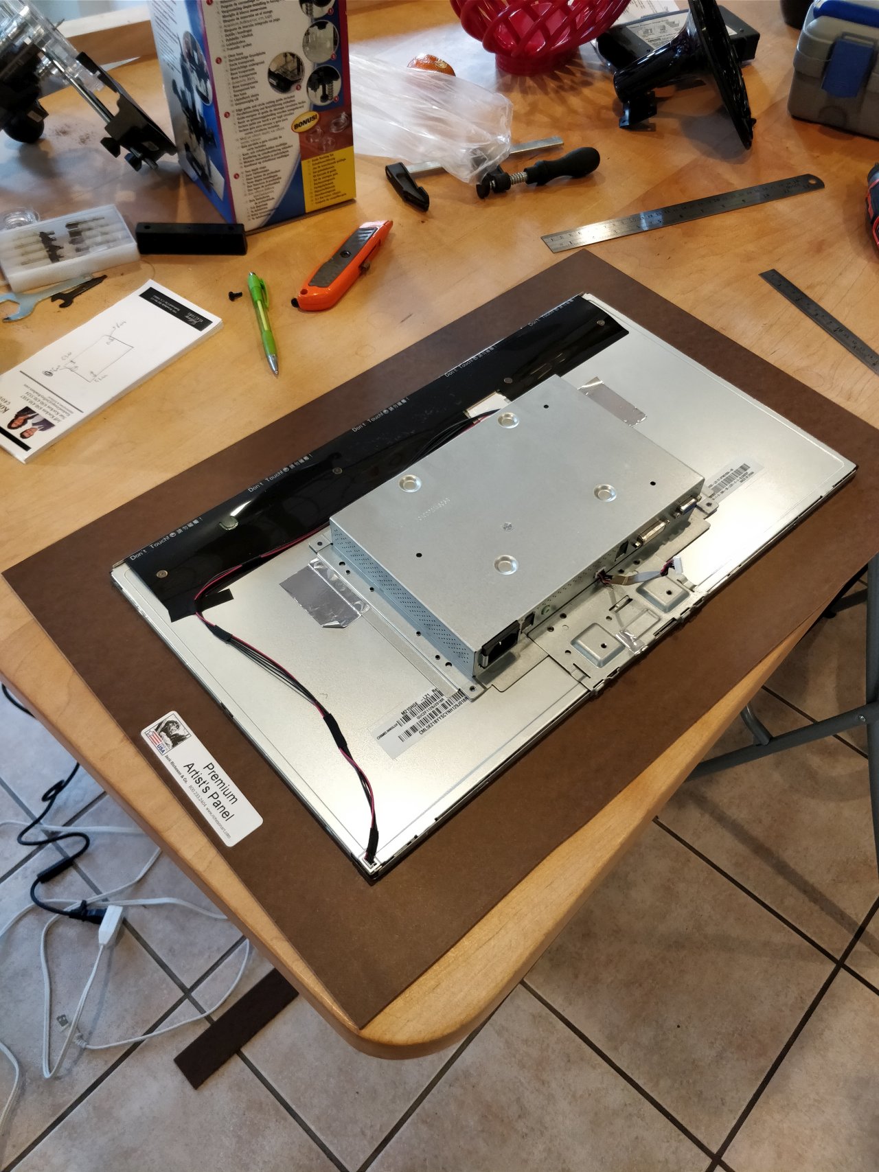
Step 1: Taking apart your wife’s monitor
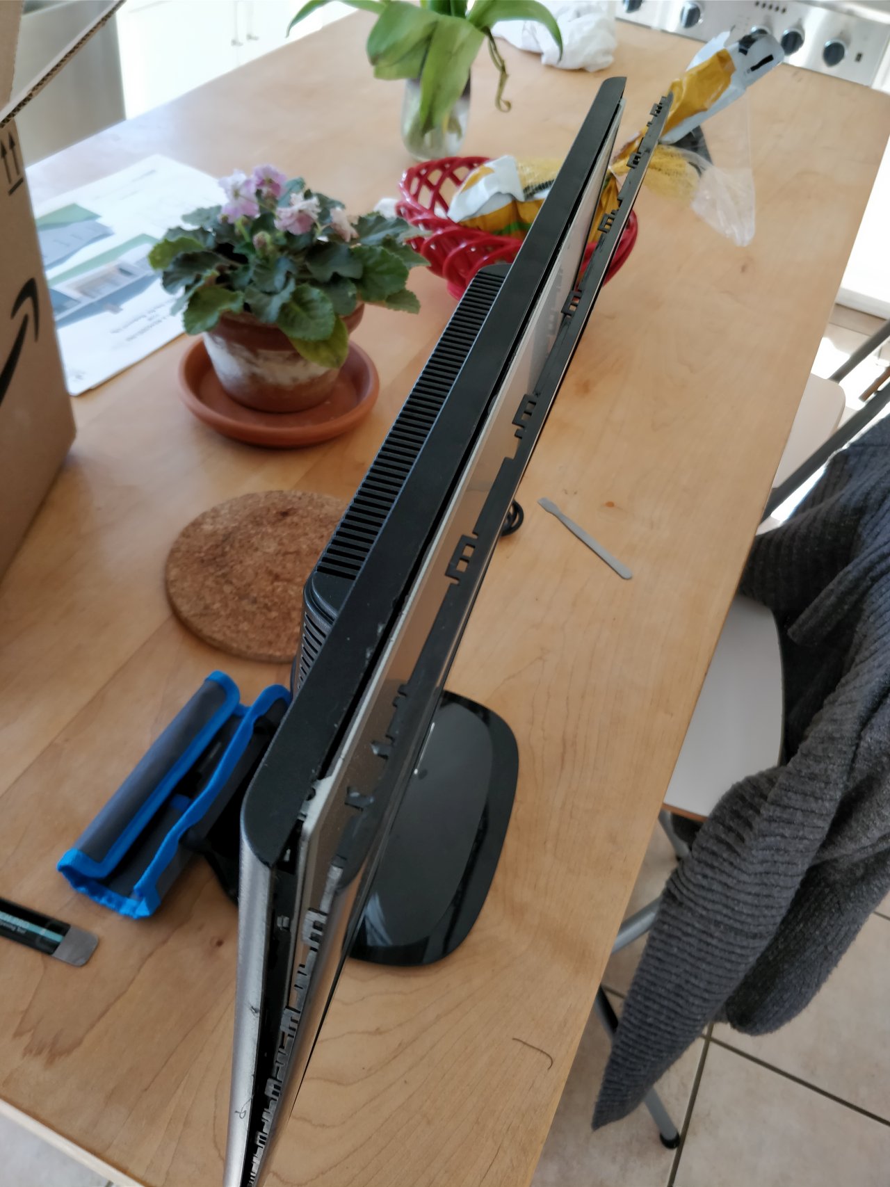
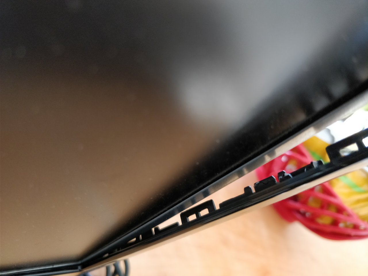
It didn’t come with any instructions, but after some time, it finally came apart and spread its innards for me.
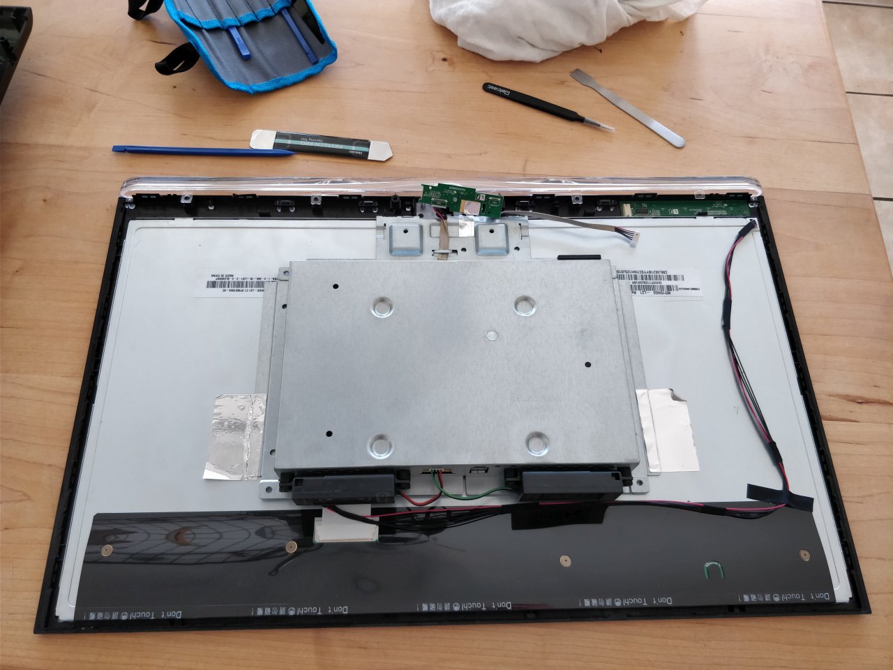
It turned out that the panel wasn’t much larger than the display itself which was handy and the controls could easily be relocated as needed. The speakers (the black boxes at the bottom) were easy to remove and lie at the bottom of the trashcan today. The drawback was that the power was built-in and added a fair amount of bulk.
But hey, free monitor, hard to complain.
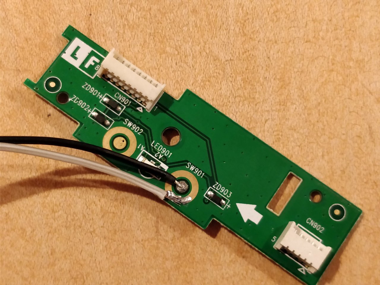
Step 2: Retain control
Next step was to solder on some buttons to replace the touch and membrane design that was used.
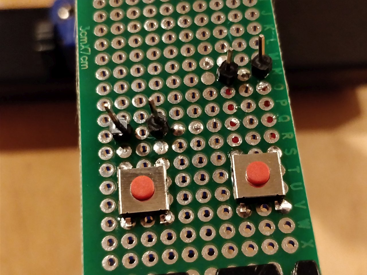
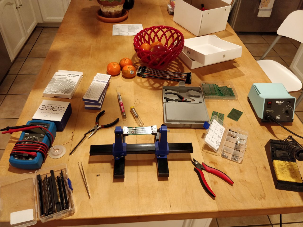
It helped that I invested in some extra hands
Not too shabby for a software engineer, no? (yeah yeah, don’t worry, I won’t quit my day job)
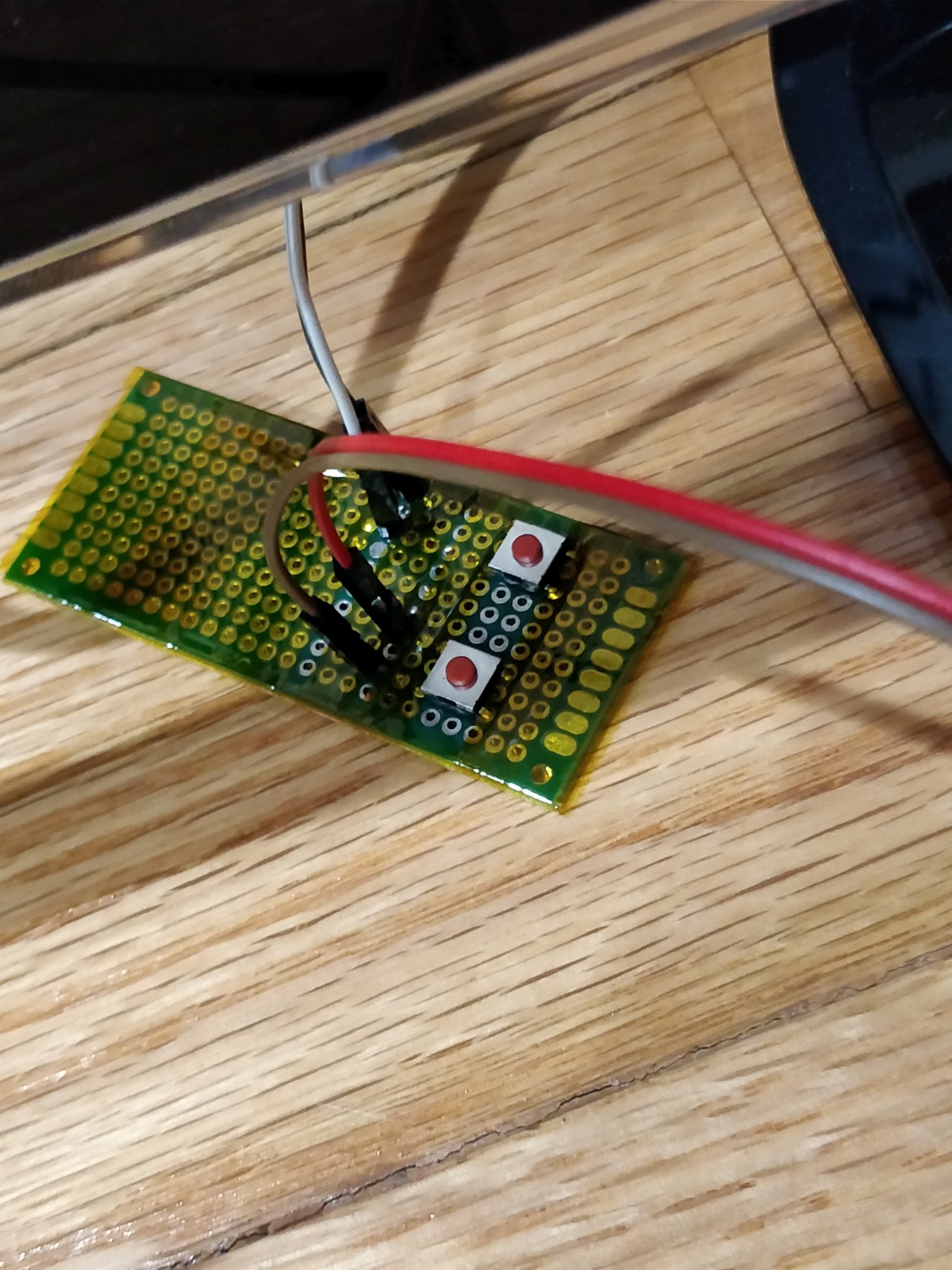
Nothing that a bit (or a lot) of kapton tape cannot fix :-)
Intermission
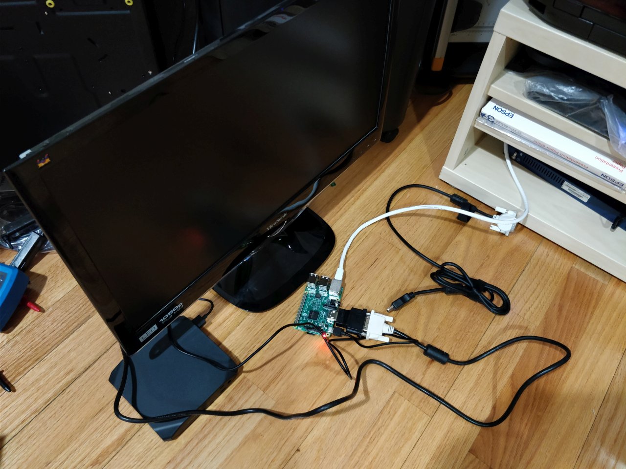
A quick testrun with all parts assembled. And it worked, I promise :-)
Okay skeptics, here’s a video
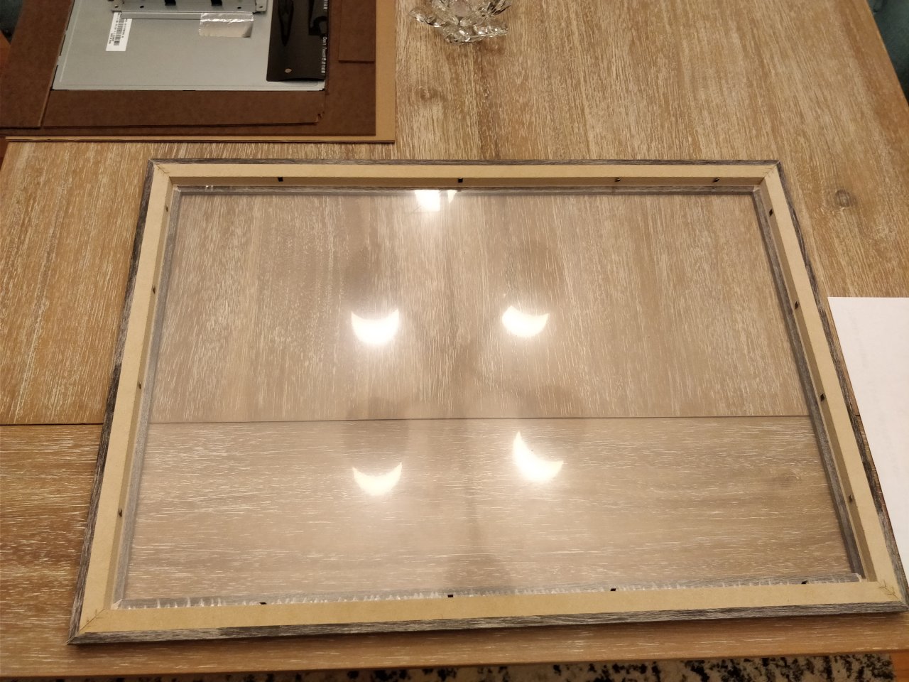
Step 3: Finding a new home
After having dismantled the monitor, it was time to find it a suitable home. Something which makes it feel more upscale and more befitting than a raw metal casing.
Enter the distressed wood frame. At 24x16 inches big, more than enough to fit the panel with some room to spare. Also making a guest appearence is the trusty HDF … What? not MDF you ask? Well, I got a bit carried away, especially since we’re talking about a monitor here. I didn’t feel like getting any flex in the construction.
Step 4: Remodelling
As you guessed (well, I told you actually), the frame was much bigger than the display and it was time to make it all fit. After some careful measurements,
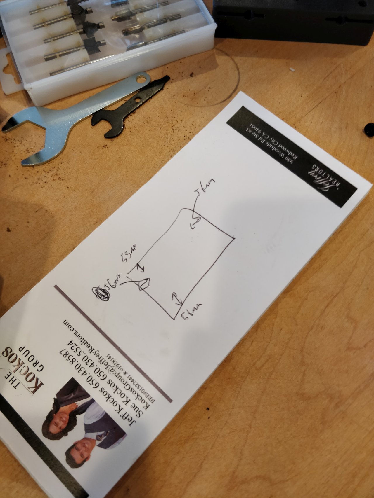
I went to work with my figure saw and dremel
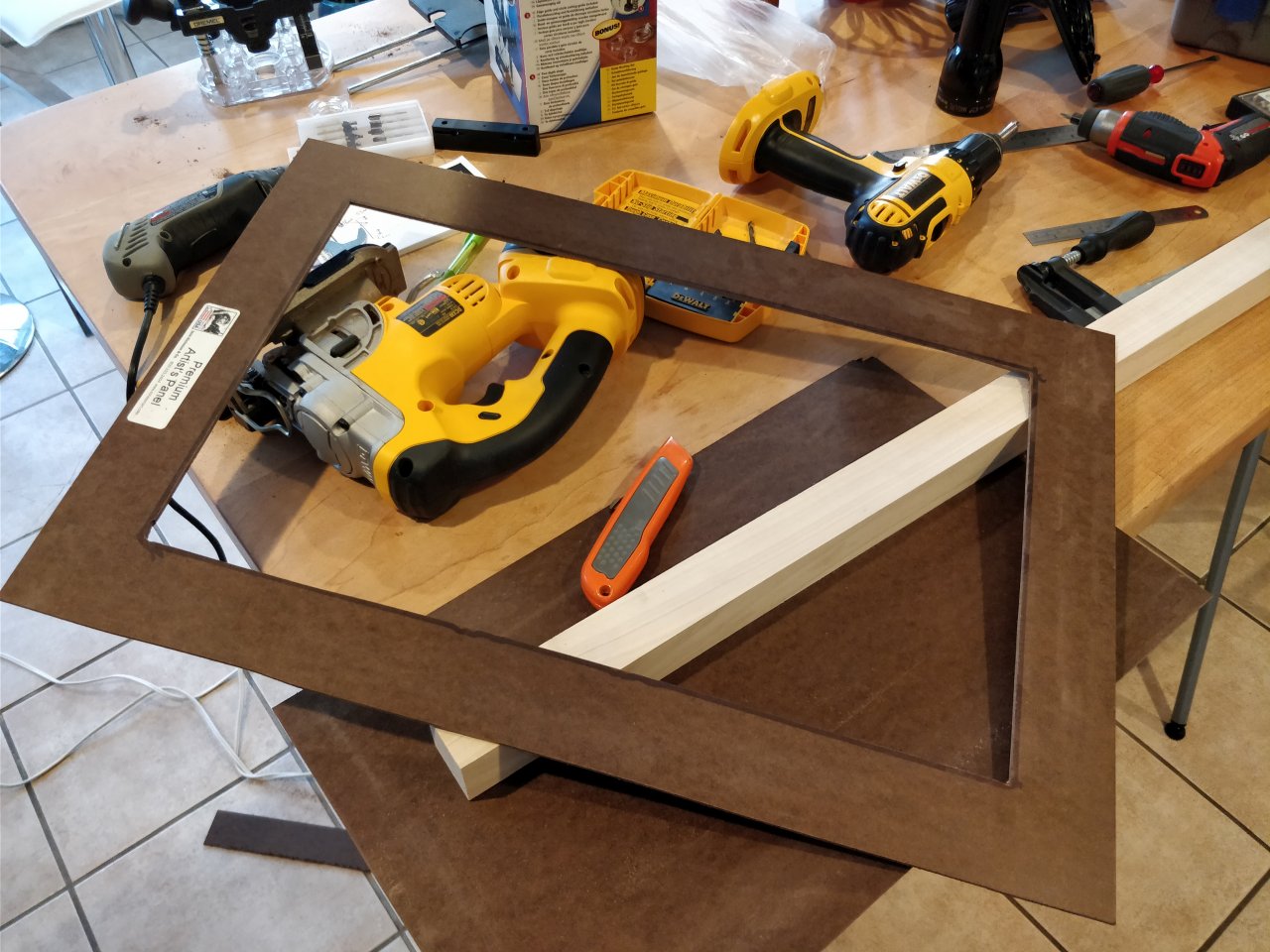
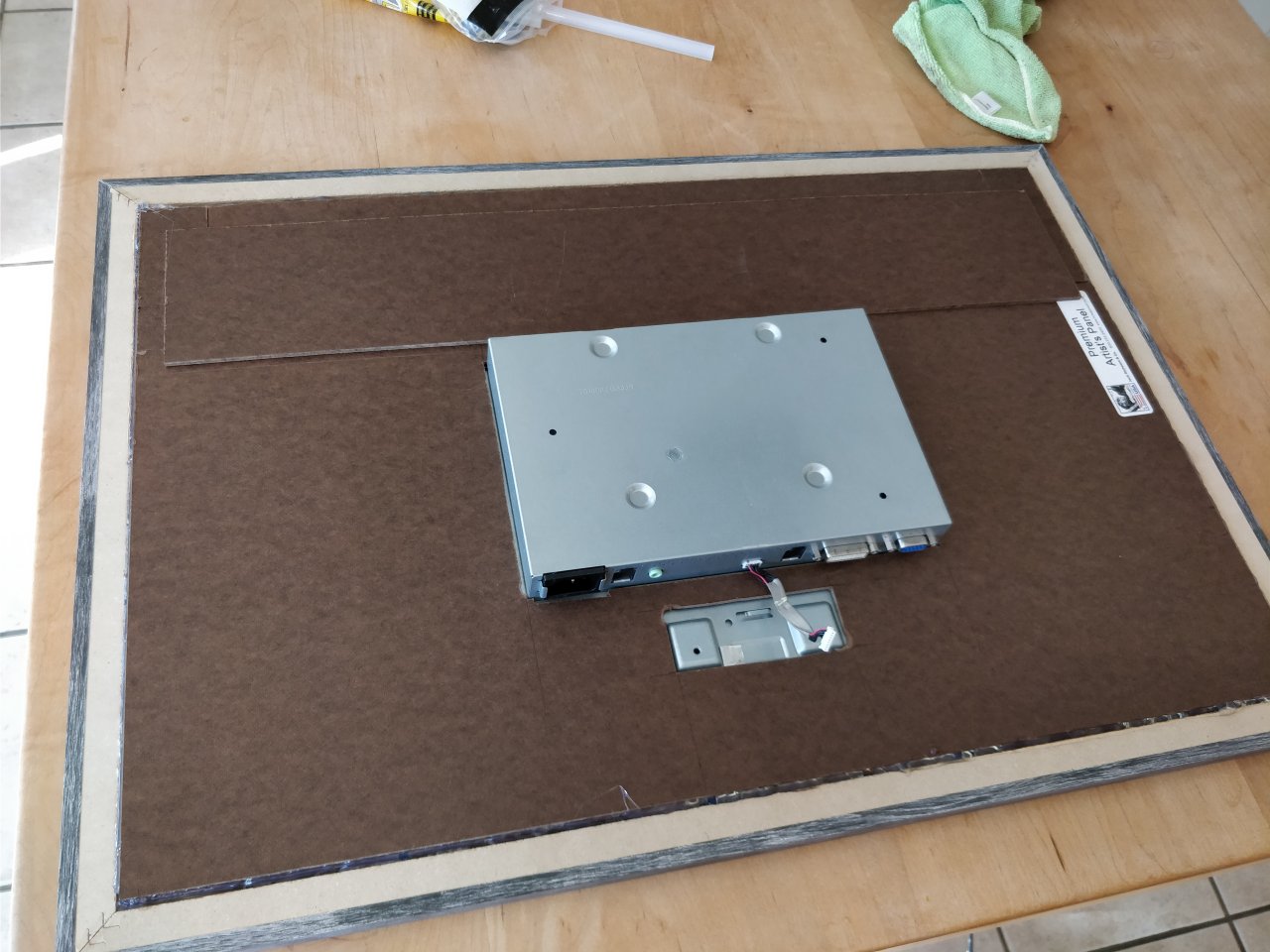
And before long, I was able to gently fit the display and HDF inside the frame
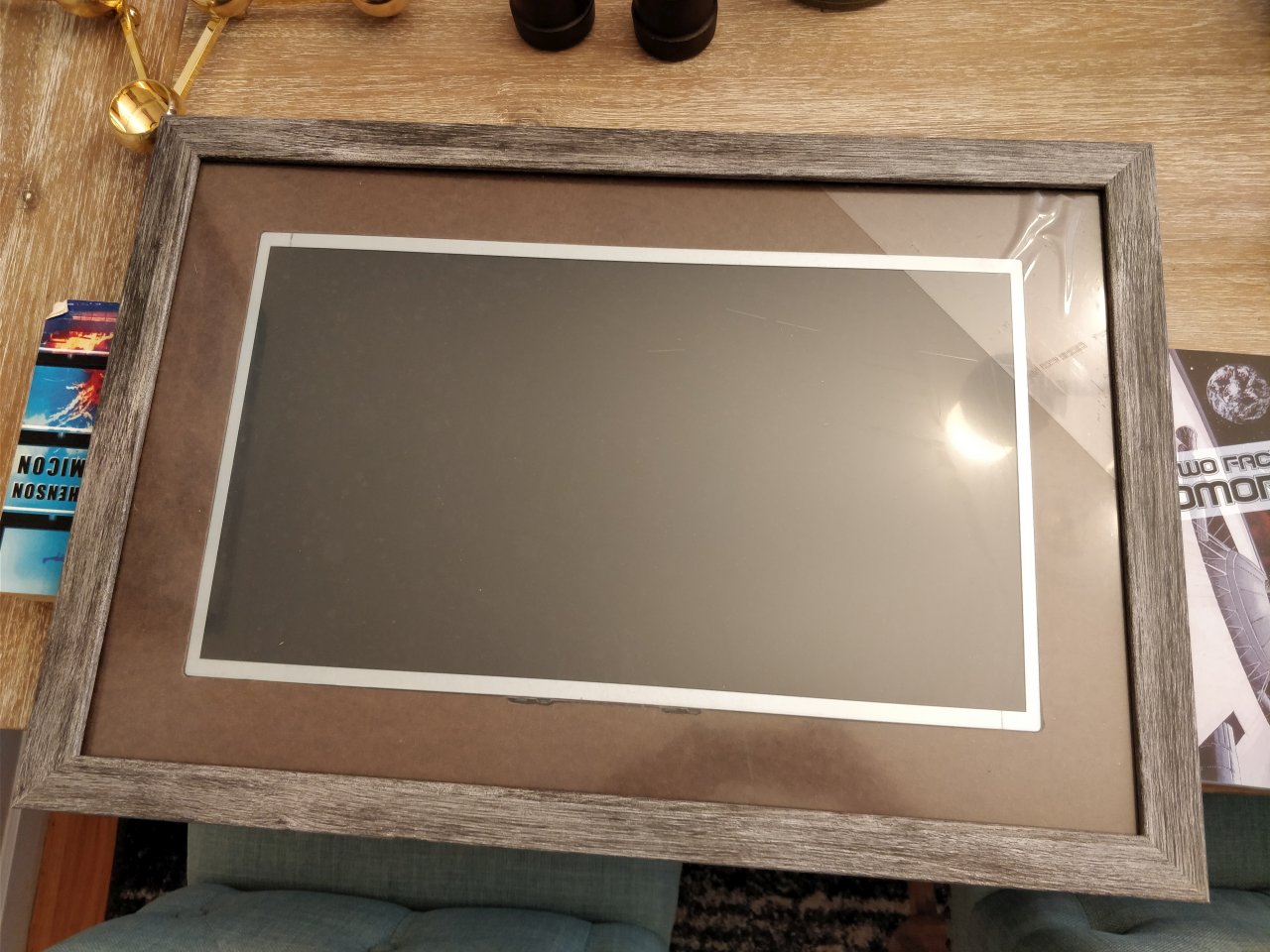
at which point I realized I was missing something… One quick visit to Michaels and I was back
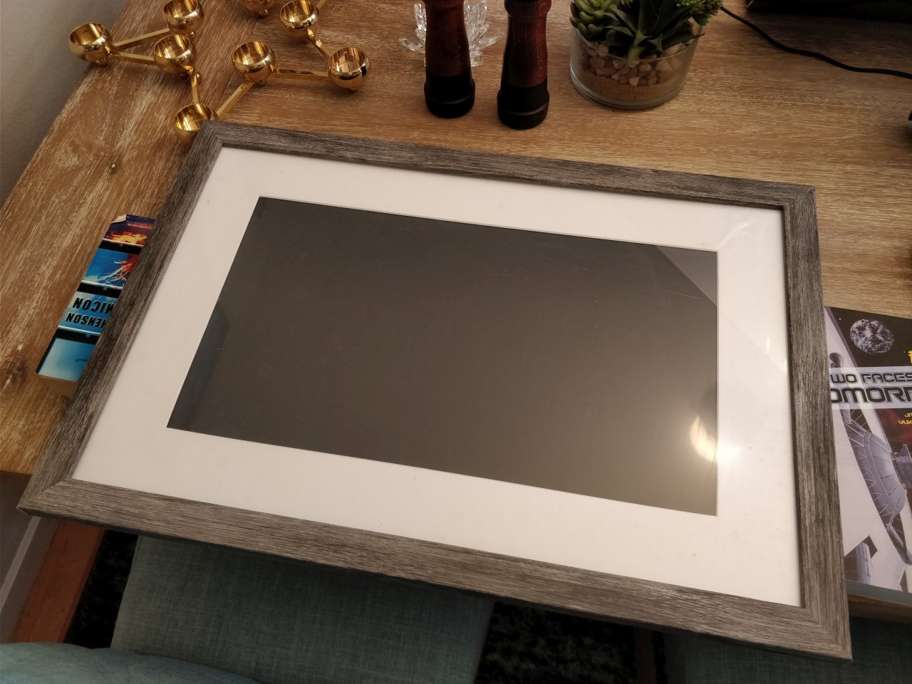
now with a white mat, which made it look a heck of a lot better.
Step 5: Securing it
First, I had some brilliant ideas for how I was going to make the display stay inside the frame
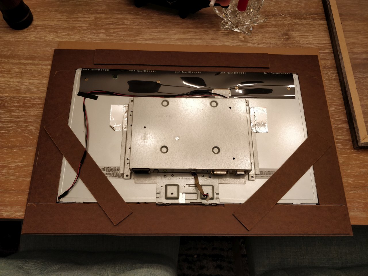
But as the work progressed, it became clear I needed to make it a bit more sturdy and secure to avoid having the panel falling out the back. So I essentially layered more HDF into the frame and display using glue between HDF pieces and doublesided foam tape between the panel’s backside and the HDF. This helped me keep things where they were supposed to be. It also avoided pinching the panel which was something I was worried about.
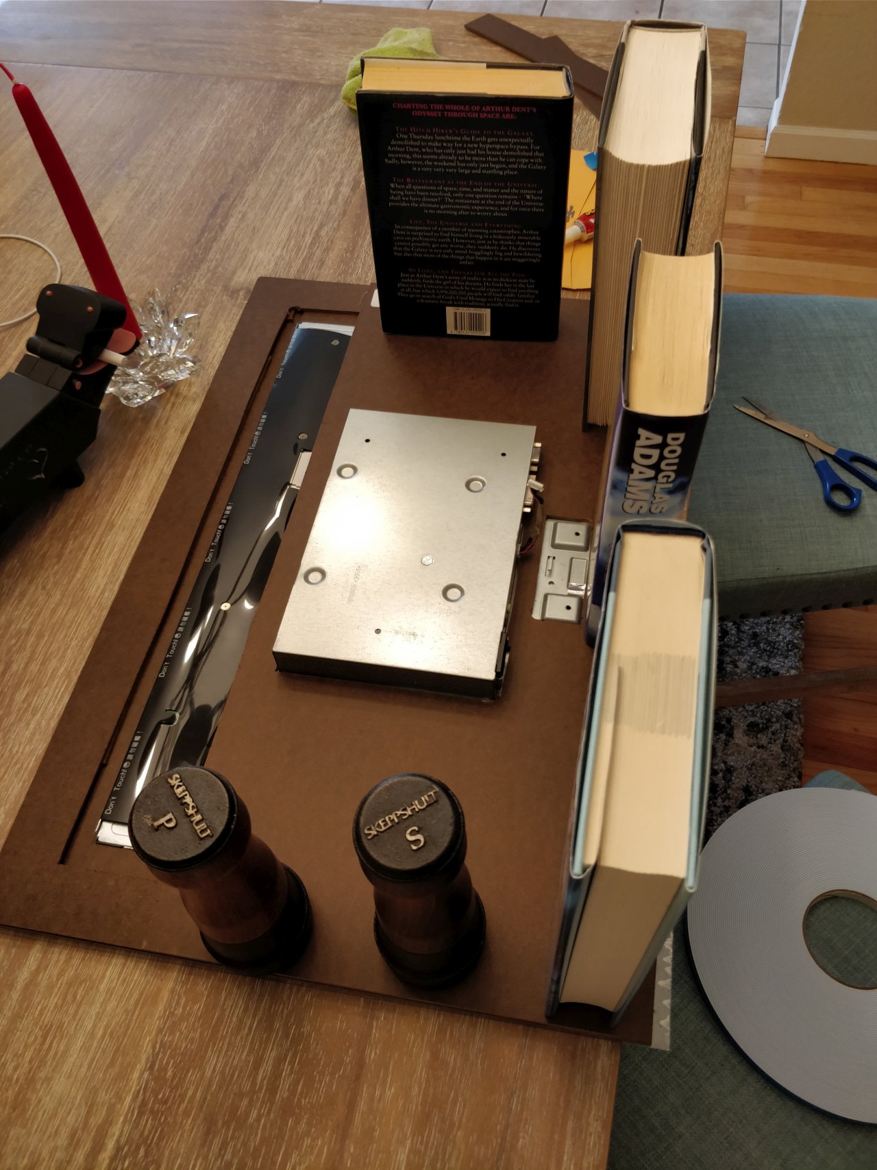
Some hours later, the glue had cured and I now had a very nice back on my frame.
Next, I needed to make sure it would not fall out of the frame.
Enter the glue gun. And not that puny “craft” glue gun, oh no. Bring forth the industrial strength dewalt one! Oh yeah!
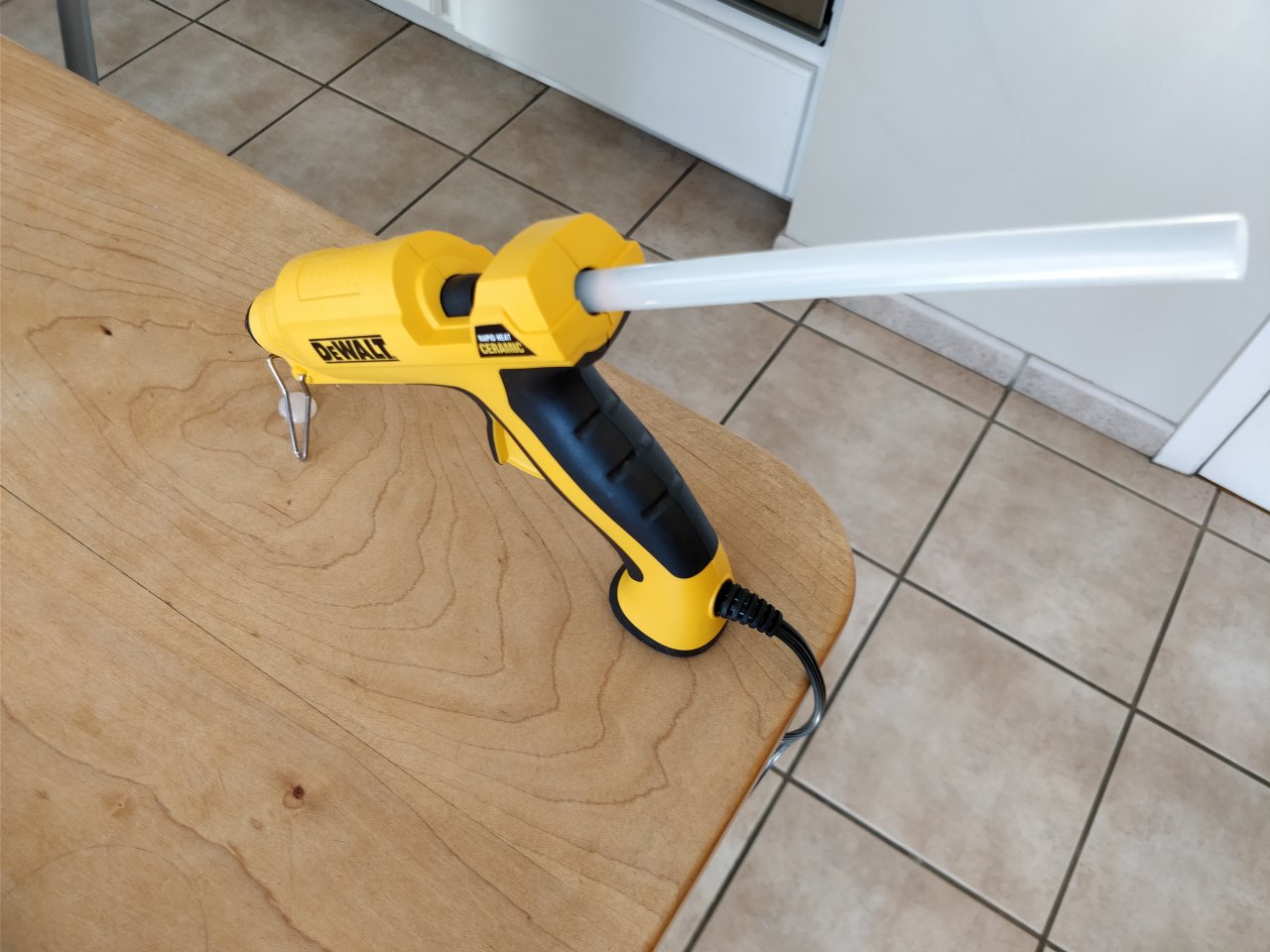
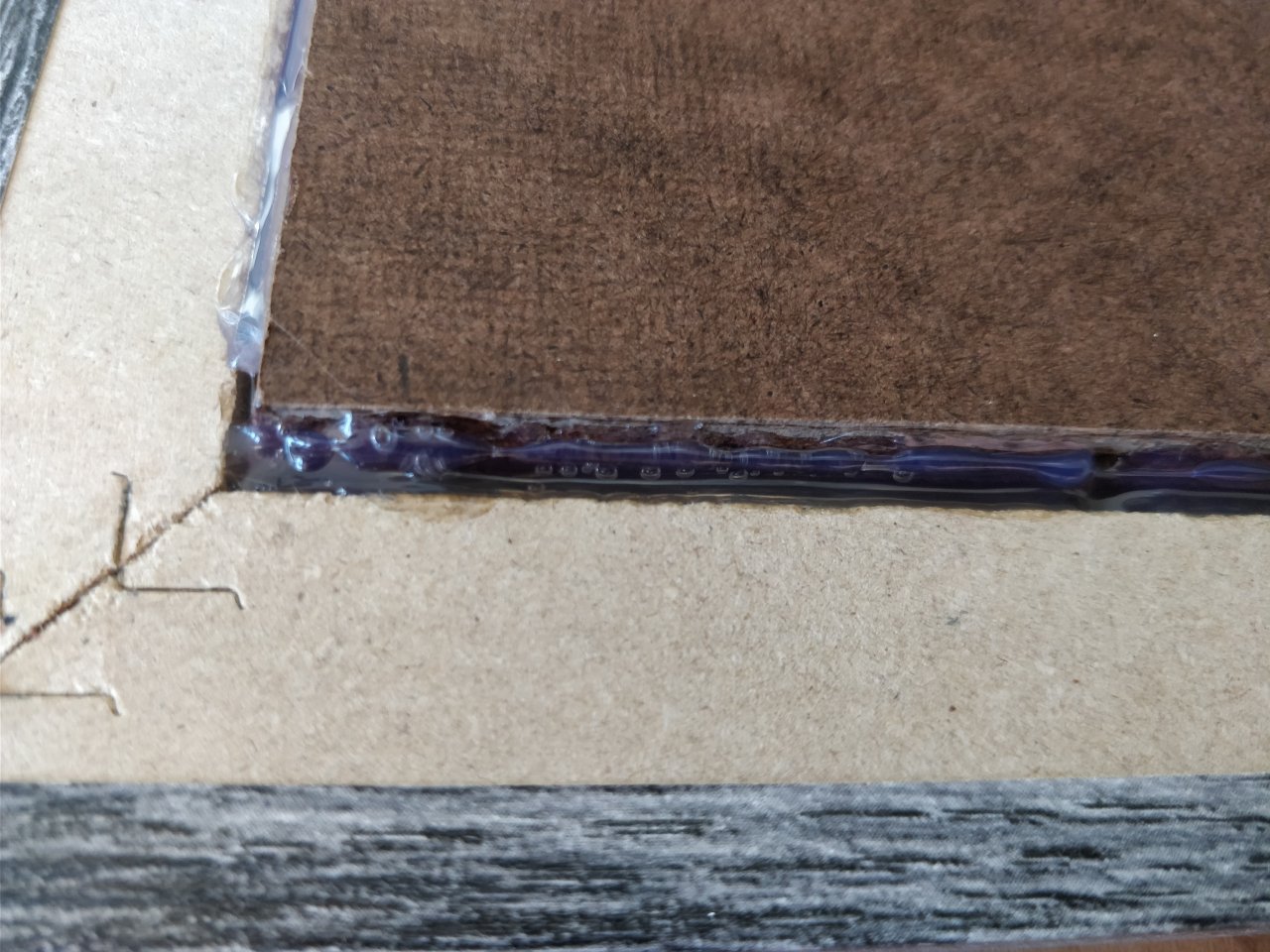
By filling in the gap between the HDF and the frame, I made sure they’d be friends forever (they better, used 5 sticks of glue)
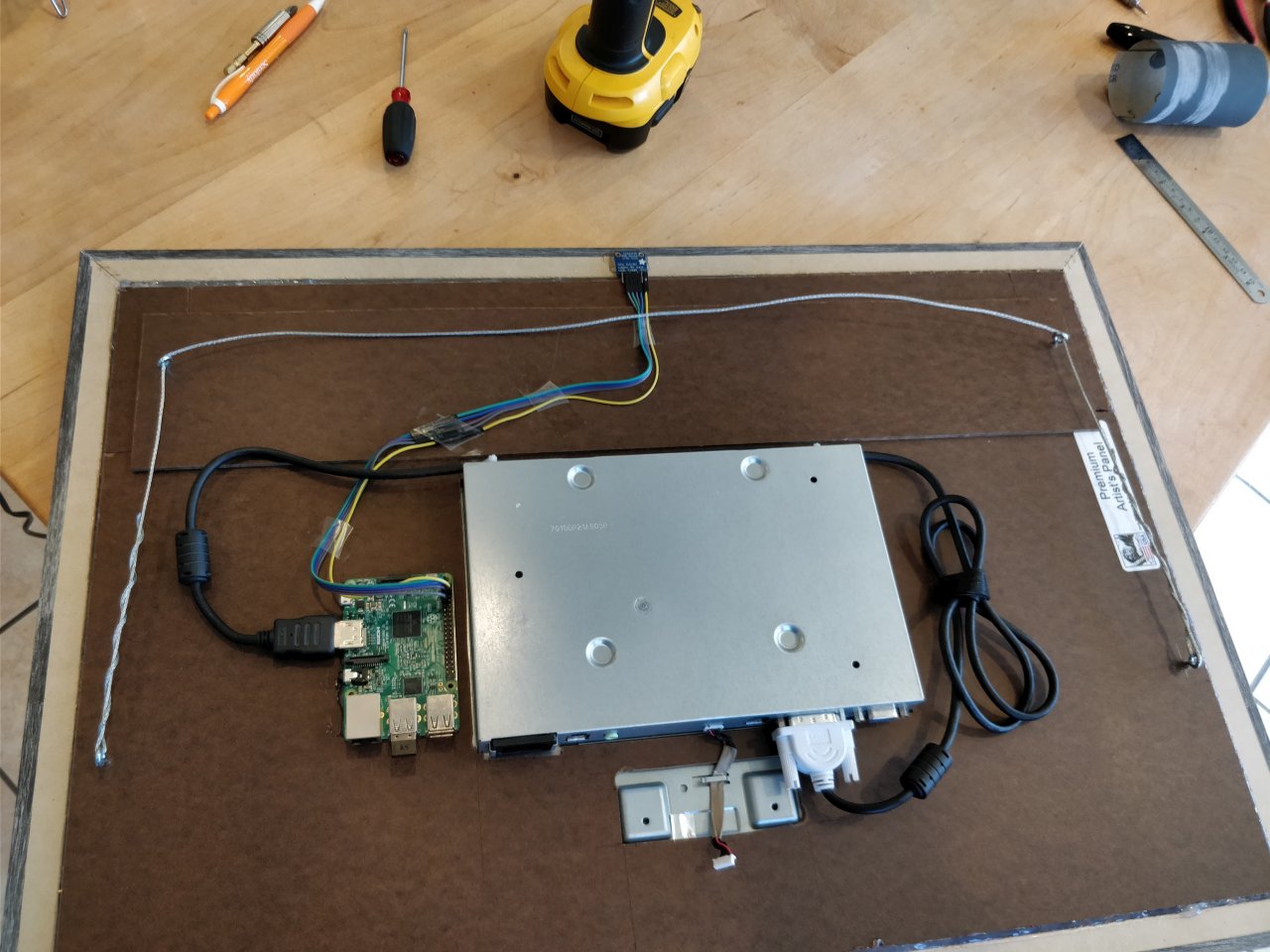
Step 6: Wiring things up
Now I had to figure out a nice way of mounting and hooking up the Raspberry Pi 3 to the display. At this point I was regretting not having a more modern screen with USB output (but on second thought, that would probably not have been enough amps anyway). After debating wether I should get a case, build a case, or something else. I decided to go with something else.
I simply glued the darn thing onto the frame. I guess I got a bit carried away
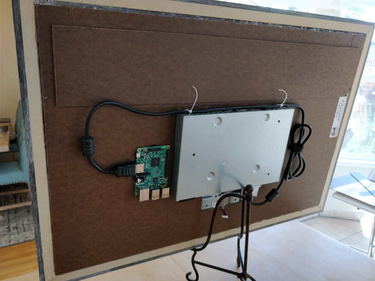
It was also at this time I found that I didn’t even need the controls for the monitor, it happily started up without a hitch or prodding, so I ended up just leaving the connector for the controls available but not connected. Less mess.
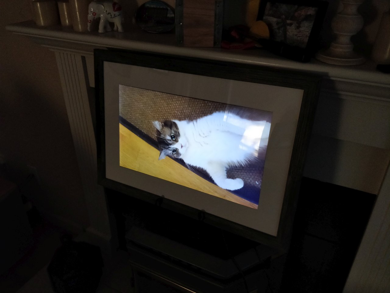
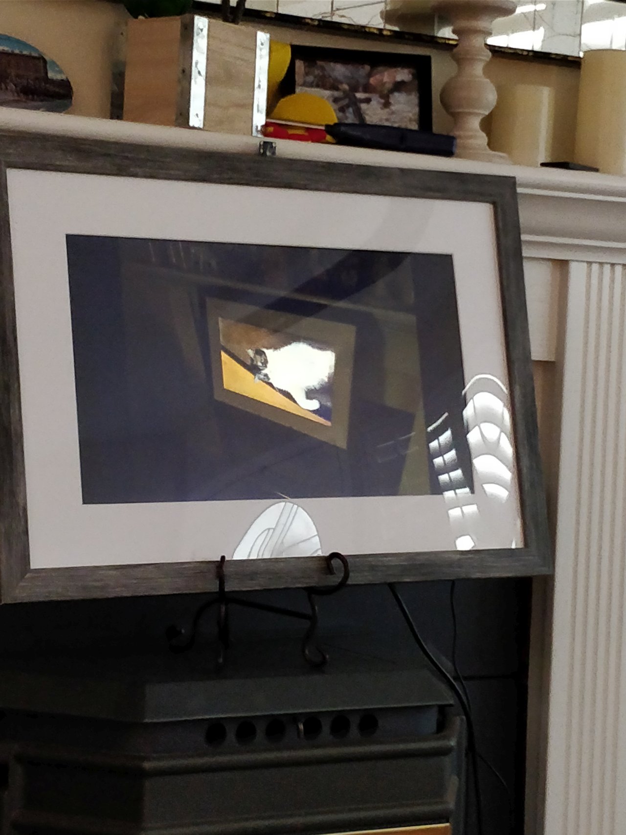
At this point, the photoframe lives! Hurrah!
(queue poorly taken photo in the dark with obligatory cat)
Step 7: Getting high on success
Now that it worked, I was starting to think, maybe I can do more? I think it took less than 1 minute and then I realized what my frame was missing.
Color temperature calibration … I know, right? Sounds fancy. But what it really means is that you interpret the current definition of white in a given image. Kinda how your camera sometimes makes your photos look blue/green/red-ish. It’s usually referred to as whitebalance.
Anyway, for a photoframe it would mean to adjust the image shown on the screen so that it matches the ambient color temperature (or whitebalance) of the environment.
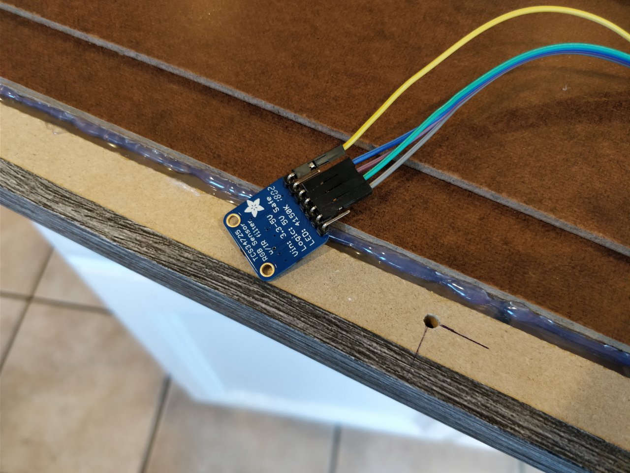
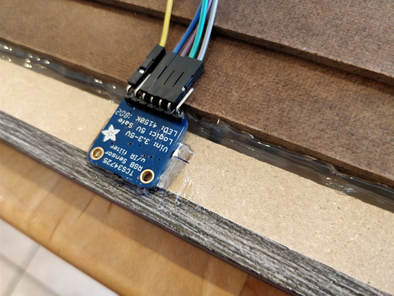
So off to the internet I went and looked for a solution. It didn’t take me long to find the TCS34725 sold by Adafruit.

It’s a $7.95 sensor that will do just that. Well, it actually does more, it can also detect how bright it is, etc. But for my purposes, this was perfect. And not only that, code for how to use with a Raspberry Pi 3 was readily available. So…
I got one
Step 8: Installing a color temperature sensor
This turned out to be MUCH easier than expected. The main concern was how to get the light to the sensor, especially since I didn’t want to have the sensor exposed (already tried that)
In short, it failed the spouse acceptance factor.
Instead I got some nice clear plastic sticks from Amazon and some 1500 gritt sandpaper so I could make sure it still was clear after being cut.
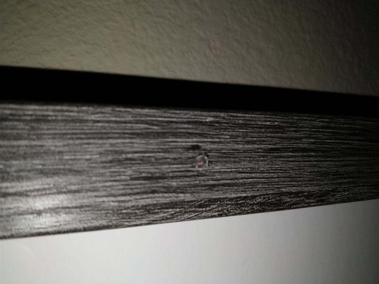
Next I drilled a hole in the top middle part of the frame and cut a plastic stick to size and then sanded it down. It fit perfectly, well, except for the fact that my distressed wood frame was actually some kind of veneer and it got a bit “damaged” when I drilled, which in turn made me a bit distressed (because changing frame now was not an option).
But it turns out that using a regular pencil to paint the exposed wood (particle board) was a perfect match for distressed wood finish and the end results are pretty darn good.
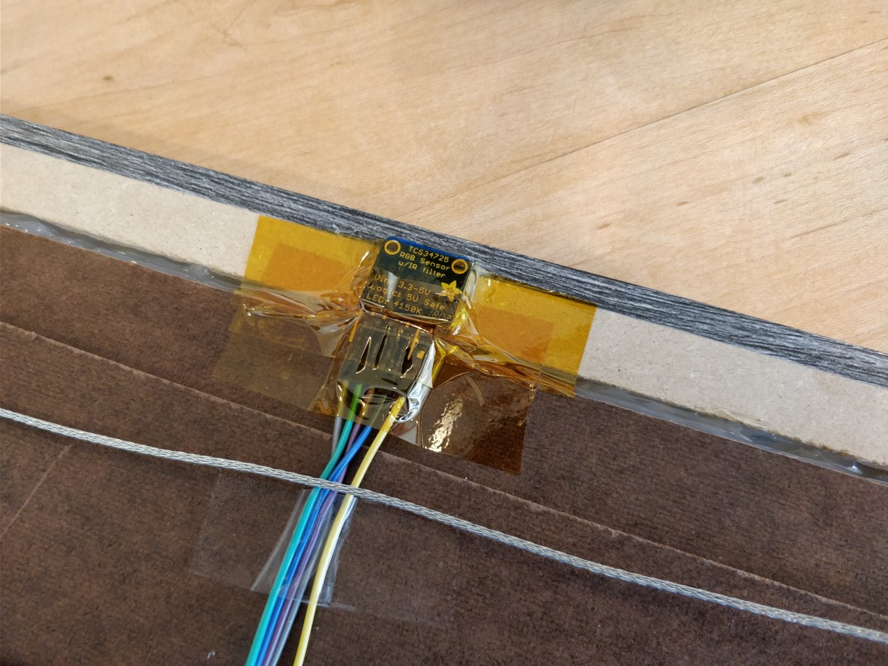
Yeah, I agree, not the best photo. But you get the idea. All that was left was to secure and protect the sensor, enter my old friends Dewalt and Kapton.
Step 9: Getting the picture
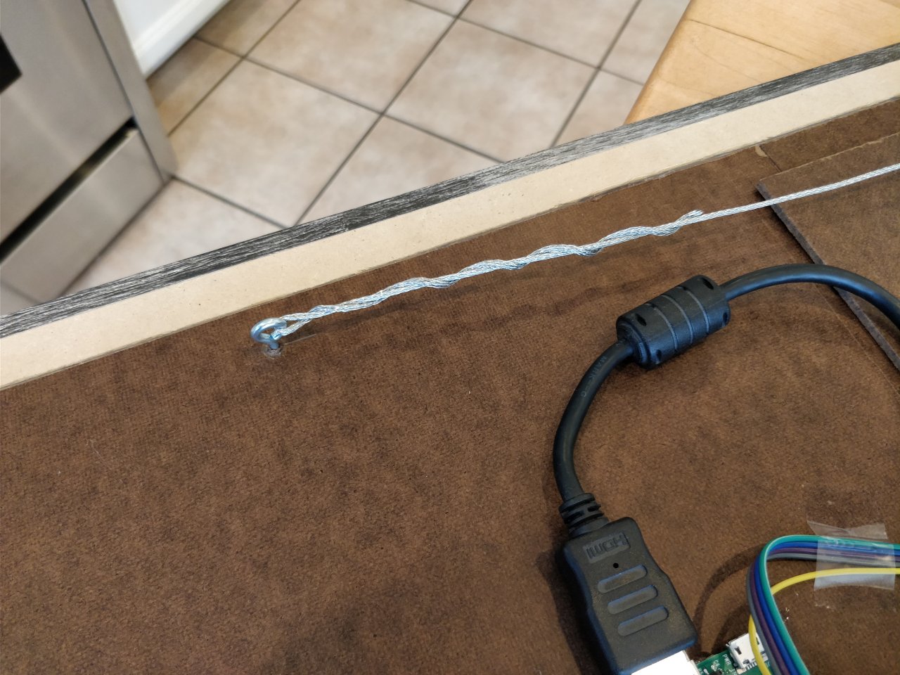
Time to go big, time to mount it on the wall. This is the point at which I realize that using HDF might not have been the smartest move. Sure, the frame is sturdy and has very little flex. But on the other hand it also weighs a ton. Which is less than great when you intend to hang it on the wall.
But after some thinking and measuring, I concluded that it was total realistic to use metal wire and some screw-in loops. This was entirely based on some humming and hawing and trying to recollect the classes from 10th grade that taught us about force distribution.
So far, it has panned out
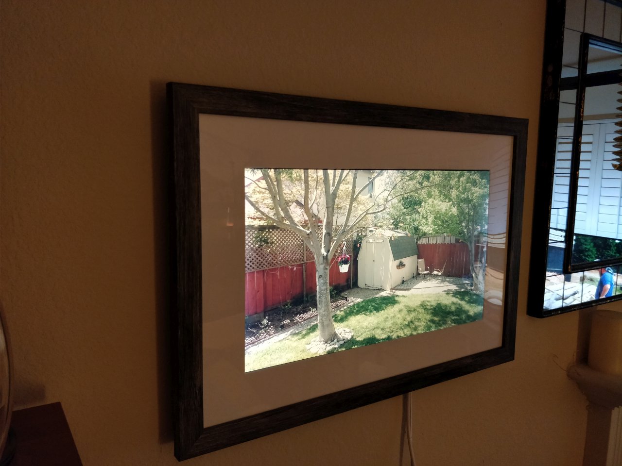
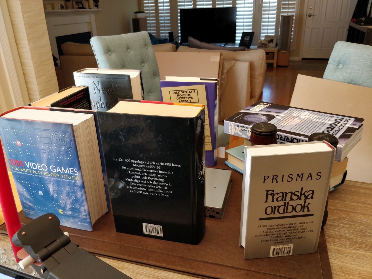
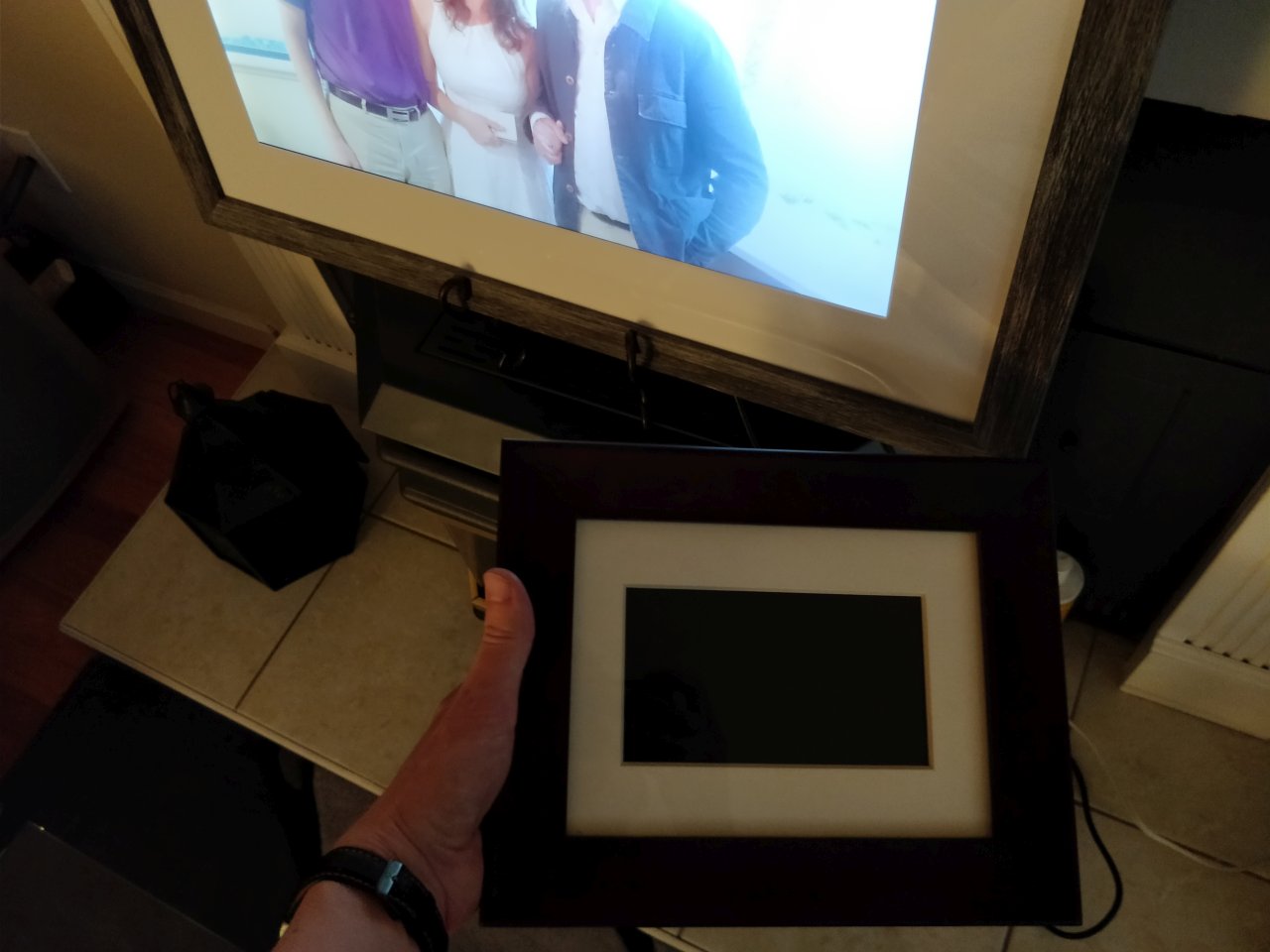
and it’s quite a bit nicer and bigger than ye digital photoframe of yore
Step 10: It’s the inside that counts
So what makes this digital photoframe worth the effort compared to the previously mentioned devices?
Well, if you just look at the raw parts, a Raspberry Pi 3, SD card (16GB) and 1080p 24” monitor with cable to connect to the Pi, you’re looking at roughly $160 plus tax. Which is pretty darn good. Price only gets better if you have any of these parts already. Heck, you might even be able to run a 4K screen to the RPi3 (not tested, so your mileage may vary). And of course, why stop at 24”? Heck, why not try 21:9 aspect ratio screens? Or ye oldie but goodie 4:3? Options are endless :-)
Secondly, this frame does not require any downloading of images to local storage or uploading to a third party service. Nor do you need to sort through your images. All you do is add a number of queries for Google Photos and it will automatically cycle through all images (at random) from all queries (also at random). It means that if you like cats, you just add a query saying cats and presto, it will show you all cat photos you have and any new ones you’ll take (cudos to you if you noticed that it actually happened to me in the pictures shown above).
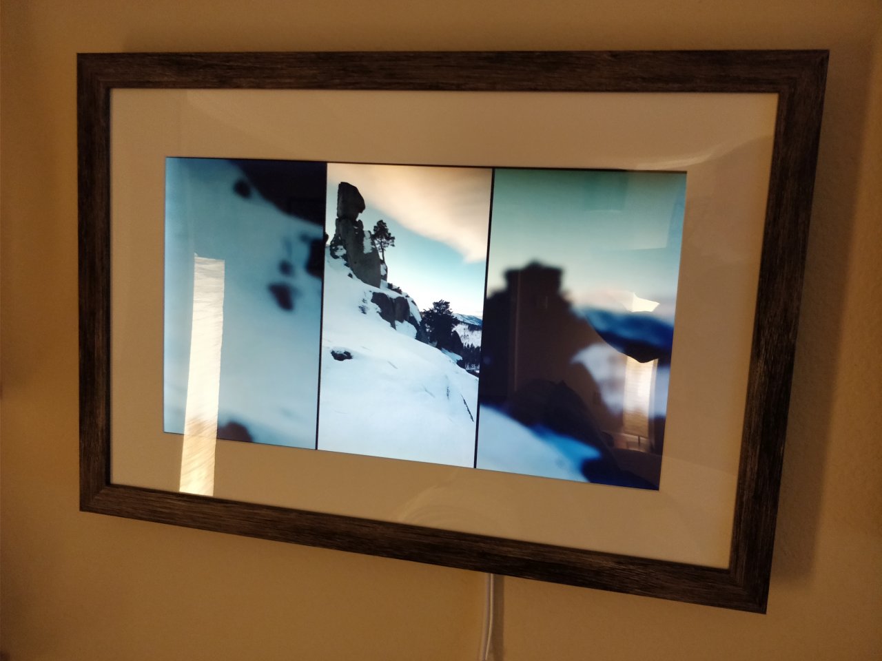
And unlike other frames I’ve seen, this one will deal gracefully with images which aren’t a perfect size for the display, by layering it and bluring the images (see above).
Lastly, it can optionally use a color temperature sensor for $8 dollars to match your photos to the room’s ambient color temperature. Granted, it might need some tuning, but I’ve noticed that for the most part it’s on-par and melds better with the surrounding.
Oh, and it’s open source. Allowing you full access to the code that runs it so you can tweak it to your hearts content.
Great! How do I get one?
Simple, just follow these instructions